- Products
- Markets
- Newsroom
- Tools & Resources
- CSR
- About Nexans
- Search
- Contact us
- Compare
- Sign in

FAQ on the laying and use of cables
Temperatures
The construction standards of the regular installation cables determine the permissible ambient temperature during operation within the range -15°C to 60°C.
Upper range limit
If the environment becomes too hot, it will heat up the cable in addition to the heating caused by the joule effect. This shortens the lifespan of the cable and increases the risk of short circuits.
Please note: This permissible maximum ambient temperature of 60°C also applies to fire-resistant cables. Fire resistant cables can withstand the high temperatures reached during a fire for a limited period of time (1 to 2 hours), but will then carbonise and need to be replaced.
If higher ambient temperatures are expected, suitable cable types must be selected.
Lower range limit
The permissible minimum ambient temperature is also important. Cable materials become stiffer under the influence of cold.
If the cable has to operate at colder temperatures, rules of good craftsmanship must be followed carefully:
-
The cable must not move at all after installation. This means that it must not be moved and absolutely not exposed to vibrations. This can cause cracks, as the cable materials are very stiff due to the cold.
-
The cable fixings must of course also be able to withstand the expected freezing temperature - if they were to shrink under the influence of the cold, they could squeeze the cable sheathing to such an extent that the cable would become damaged in that spot.
When current flows through a conductor, it heats up through the joule effect. The more current, the warmer the conductor becomes. If the temperature of the conductor rises too high, its insulation layer will begin to melt, which may lead to short circuits. The maximum admissible conductor temperature is therefore limited by the insulation material around the core.
-
maximum core temperature of 70°C for cables and wires insulated with:
-
Halogen-free compounds (ex. H07Z1-R)
-
Pvc (ex. H07V-R)
-
Rubber (ex. H07RN-F)
-
-
maximum core temperature of 90°C for cables and wires insulated with:
-
XLPE (ex. XGB, XVB)
-
Halogen-free material 90°C (ex. H07ZZ-F)
- Pvc 90°C (ex. H07V2-K)
-
Ideally the ambient temperature at installation or installation temperature should not be lower than 0 or 5°C. Cable materials become stiffer at low temperatures. Manipulating the cable at such temperatures can cause cracks, which will render the installation unreliable. The minimum temperature for installation can be found on the technical data sheet.
If you strictly observe rules of good craftsmanship, cables can be installed at low temperatures down to -20°C:
-
The cable must be kept in a heated room of at least 20°C for 24 hours.
-
During installation, the temperature of the cable sheathing must be carefully monitored. If it cools down too much (below 5°C), it must be warmed up again for 24 hours.
-
The bending radius must be strictly respected during installation. Bending a cable too far puts a lot of tensile forces on it and since the materials are stiffer because of the cold, there is an increased risk of cracks.
Bending radius
Cables can be bent, that goes without saying. But if you bend a cable too far, this considerably shortens the lifespan of your cable and you even risk short circuiting and/or causing a fire. On the outside of the bend you have after all 'stretched out' the cable materials too much - they become thinner or perhaps even show cracks - as a result of which the original electrical properties of the conductor insulation are lost. So, how do you do it safely?
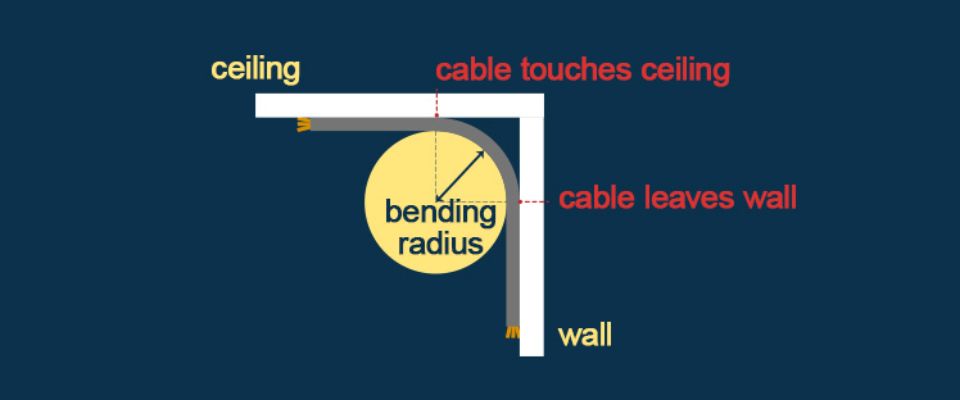
Yes, provided you respect the bending radius properly. Your cable will then bridge the angle between wall and ceiling.
It is not permitted to push the cable as far as possible into the corner to get as little as possible away from the wall and ceiling. What you would be doing then, is applying a much smaller bending radius than permitted.
-
H07V-U Eca and H07V-R Eca
-
D ≤ 8 mm : 4xD
-
8 < D ≤ 12 mm: 5xD
-
12 mm < D: 6xD
-
-
H07Z1-U Cca and H07Z1-R Cca
-
D ≤ 8 mm : 4xD
-
8 < D ≤ 12 mm: 5xD
-
12 mm < D: 6xD
-
-
Alsecure XGB Cca and Alsecure XFGB Cca
-
monoconductors: 15xD
-
multiconductors: 12xD
-
-
XVB Cca and XFVB Cca
-
monoconductors: 15xD
-
multiconductors: 12xD
-
-
EXVB Eca and EAXVB Eca : 12xD
-
EXAVB Cca and SXAVB Cca : 15xD
For unarmoured cables only, a reduction of the bending radius by 50% is allowed by the construction standards during installation, provided that the following are all applicable:
-
by a skilled worker
-
single bending, for example at a termination
-
the cable is at a temperature of not less than 30 °C or adequately heated up to 30 °C
-
and cable is bent by means of a template or preformed rollers.
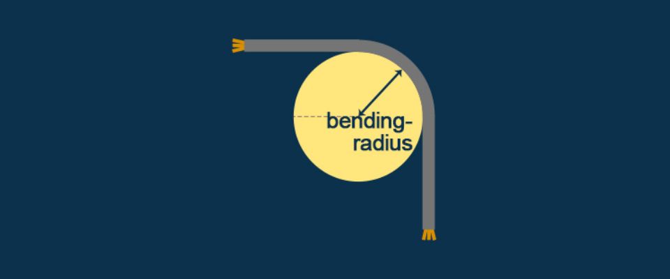
The cable should be bent around an imaginary circle whose radius is at least the bending radius of your cable.
Let us take as an example an XVB Cca 4G95 mm² of which
-
bending radius as stated on the technical datasheet = 12 x D
-
nominal exterior diameter = 35 mm (this must always be verified on the cable itself)
-
So: 12 x 35 mm = 420 mm.
This 420 mm is the minimum bending radius. The XVB Cca 4G95 mm² can be bent according to a circle with as smallest permissible radius 420 mm.
The bending radius expresses the smallest possible bend with which one can safely bend a cable without kinking, damaging or shortening its life span. The smaller the bending radius, the shorter bends you can make.
The bending radius is usually expressed as a multiple of the outer diameter of the cable, for example: 4xD or 12xD where "D" is the outer diameter of the cable. Sometimes this is already calculated specifically for your cable and is then expressed as a value in mm. Bending radii vary according to the cable type and the section. The bending radius that applies to a particuler cable is stated in its technical data sheet.
The bending radii stated always apply at an ambient temperature of (20 ± 10)°C and are always measured at the inner curvature of the cable.
Cable pulling
When laying a cable, the cable drum is unwound and the cable is led to its “location” by pulling on the end of the cable. If you pull too hard, you may damage the sheathing, or the entire cable and your installation will not be safe to operate. So, how hard can you pull on a cable?
When pulling cables, some friction between the cable and the surface is inevitable. This makes you pull harder on the cable, which inadvertently can cause damage to the cable or sheath. By using adapted cable guides and cable rolls, that friction is reduced, reducing the need for pulling force and reducing the risk of damage.
Not only the correct guidance is important, but also the correct bending radius.
-
Copper core: pulling force P = S x 50 N/mm²
-
Aluminium core: pulling force P = S x 30 N/mm²
wherein S = sum of the section of all conductors in mm², without counting any screen or armour.
Cables should be pulled into place by using appropriate pulling devices ensuring that the pulling force is evenly distributed on the cable conductors. The maximum pulling force varies according to the device used, and the configuration of cables being pulled. The pulling force shall be permanently supervised
during the pulling procedure.
The maximum pulling force during installation is defined in the construction standards, which differentiate between pulling with a pulling head or with a pulling sleeve.
- Cable without armour, without metal sheathing
-
Copper core: pulling force P = S x 50 N/mm²
-
Aluminium core : pulling force P = S x 30 N/mm²
wherein S = sum of the section of all conductors in mm², without any screen
-
- Cable with steel wire armour*
-
Copper core: pulling force P = D² x 9 N/mm²
wherein D = cable diameter in mm
-
- Cable with steel tape armour*
-
Copper core: pulling force P = D² x 3 N/mm²
wherein D = cable diameter in mm
-
(*) values taken from the German VDE construction standards
Installation depth
Cables are usually installed at a depth ranging from 70 cm to 120 cm.
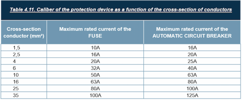
Cross-section determination
For domestic installations, the AREI/RGIE (General Regulation on Electric Installations) defines the maximum rated current of the fuses or the size of the automatic circuit breaker protecting a cable, according to the cross-sectional area of the conductors in Table 4.11.
This table does not apply to industrial installations.
When determining the section of fire-resistant cables, the increased resistance of the conductors and the increase in voltage drop due to the high temperatures that can be reached in a fire must be taken into account. The AREI/RGIE indicates that account must be taken of the compartment in which the greatest voltage drop occurs but it does not provide any concrete calculation method for the determination of the section.
The Wiedemann-Franz method is based on the laws of physics and takes compartments into account. The Wiedemann-Franz formula is only one of the possible approaches to the problem and in no way implies disapproval of other rules of good practice.
Download the calculation method (in Dutch or French only)
Not totally at ease with this calculation? Did you know EasyCalc also calculates the cross-section of fire-resistant cables? Its calculations are based on this Wiedemann-Franz method.
Suppose:
-
Required current = 125 A
-
3 phases + earthing 400V
-
Cable type XVB
-
Length = 15 m
-
Special features: The cable will be installed on a well ventilated cable duct, where two other energy cables are also laid (joined). The cable is installed in an area where the ambient temperature regularly reaches 40°C.
Application of the derating factors:
The initial cross-section determination indicates that an XVB 4G25 mm² is required to transmit a current of 125 A. This initial current of 125 A must then be divided by the derating factors based on the installation and environmental conditions:
-
derating due to high temperature: 125 A / 0.91 = 137.4 A
-
derating due to the proximity of adjoining cables: 137.4 A / 0.8 = 171.8 A
Conclusion: a section with an Iz higher than this result of 171.8 A should be taken. Concretely: an XVB 4G50 mm² which has an Iz of 192 A.
You don't want to have to do the calculations by hand each time? Did you know our free tool EASYCALC does it for you?
The proximity of other energy cables and other installation conditions influence the heating up of the cable. Therefore, the nominal load values must be combined with the various derating factors in order to adapt the current to the real situation.
A correct cross-section determination therefore takes into account both the required current and the derating factors. Please note that depending on the actual installation conditions, several derating factors may apply.
Download the derating factors for LV installation cables (in Dutch & French only)
The permissible maximum current - also designated by Iz or Imax - of a cable stated on the technical data sheets applies to the following standard conditions:
Laying underground:
-
Ground temperature: 20°C
-
Thermal resistivity of ground: 100 K.cm/W
-
Laying depth: 70 cm
-
Number of cables/system: 1, without other cables in the proximity.
-
Trefoil laying for single core systems.
Laying in air:
-
Ambient temperature: 30°C
-
Installation on an open and ventilated cable tray
-
Number of cables/system: 1, without other cables in the proximity (not in a bundle or layer)
-
For XGB and XVB single cores: based on 3 conductors in trefoil
-
For H07Z1-U & -R and H07V-U & -R based on 3 conductors in conduit, integrated in a wall.
Derating factors must be applied in all other installation conditions.
Our tool for cross-section determination EASYCALC takes the right derating factors into account when determining a cross-section.
When calculating the cross-section, you should take into account:
-
Heat:
-
The selected section must be such that the heating caused by the currents passing through it does not exceed the allowed conductor temperatures. Overloading the cable must be prevented.
-
One or several derating factors must be applied according to the actual laying circumstances and environment of the installation in order to take into account the actual currents in service.
-
-
Voltage drop:
-
A voltage drop of 5% is generally permitted.
-
The distribution system operator can impose a maximum voltage drop of 3% in certain situations.
-
Higher voltage drops are allowed for the starting of motors, where high inrush currents can occur.
-
Cable types
Alsecure XGB Cca can be used outdoors without protecting it from direct sunlight. It has successfully passed the 720-hour UV aging test as per EN 50289-4-17 Method A. This method takes into account the expected amount of UV radiation for our Belgian climate.
Ambient temperatures down to -15°C are admitted, provided there are no mechanical forces (vibrations etc.) on the cable and the cable is not moved.
XVB Cca can be used outdoors, provided it is protected from direct sunlight.
Ambient temperatures down to -15°C are admitted, provided there are no mechanical forces (vibrations, etc) on the cable and the cable is not moved.
Alsecure XGB Cca is not suited for direct burial. However, it is allowed to bury it in a well-draining bushing.
XVB Cca is not suited for direct burial. However, it is allowed to bury it in a well-draining bushing.
Yes. XVB Cca and Alsecure XGB Cca have the same electrical values. An XVB Cca can perfectly be replaced by an Alsecure XGB Cca with the same cross-section.
However, Alsecure XGB Cca comes with 2 addtional benefits compared to XVB Cca:
-
The Alsecure XGB Cca range is halogen free with fire reaction Cca-s1,d2,a1 allowing it to be used in evacuation routes, premises accessible to the public or tunnels.
-
Alsecure XGB Cca cables are UV-resistant as per EN 50289-4-17 Method A - 720h test, which is perfectly adapted to our Belgian climate. They can thus be used exposed to direct sunlight.
Therre are several options:
-
The most common solution is the EXVB Eca: the cable can be laid directly underground, you just need to protect it with tiles from a spade.
-
As the EXVB Eca has a reinforced sheath, it can prove less easy to connect it to the lights. A solution is to pull the EXVB from the cabinet to a junction box, and continue the last 40-50 cm above the ground to the luminaire with the LINEAX Eca rubber cable. You then enjoy the advantage of the rubber cable for an easy connection. The AREI/RGIE does not allow the burying of rubber cables and in domestic installations it is not allowed to connect them to the switchboard.
-
XVB Cca and Alsecure XGB Cca can be placed underground as long as they are laid in a well-drained bushing.
The French U-1000 R2V Eca installation cable is commonly used in France and is sometimes used in Belgium as well as an alternative to the XVB Cca. But how to proceed correctly so that your installation is not rejected?
What is U-1000 R2V?
U-1000 R2V Eca is an installation cable for low voltage installations of 0.6 / 1 kV with PVC sheath according to French standard.
-
U-1000 R2V Eca is used in domestic and industrial fixed installations.
-
U-1000 R2V is UV resistant and may be installed outdoors exposed to direct sunlight.
-
U-1000 R2V can be directly buried with an extra mechanical protection.
-
U-1000 R2V is suitable for use at ambient temperatures between -25°C and + 60°C.
-
U-1000 R2V is insulated with XLPE (Cross-linked polyethylene) and can be loaded up to a core temperature of 90°C.
-
U-1000 R2V has Eca fire class according to EN 50575. This means that according to the Belgian AREI/RGIE (General Regulation on Electrical Installation), this cable cannot be laid in bundle or in layer in Belgium.
Comparison with XVB Cca
-
Both cable types have similar maximum permissible currents and withstand similar ambient temperatures.
-
XVB Cca can be installed outside but must be protected from direct sunlight.
-
XVB Cca may be installed underground provided it is in a well-drained bushing.
-
XVB Cca has fire class Cca-s3,d2,a3 according to EN 50575 and may be installed in bundle or layer according to the AREI/RGIE.
Conclusion
Its Eca fire reaction limits the use of U-1000 R2V in Belgium. U-1000 R2V Eca is therefore not equivalent to the XVB Cca. It is rather an equivalent to EXVB Eca.
Fire resistance
What is the fire rating of fire resistant cables in Belgium?
The fire rating of fire resistant installation cables has to be as such:
-
fire reaction performance according to NBN C30-004:
-
- fire retardant F2
-
- halogen-free: SA (smoke acidity) and SD (smoke density)
-
-
fire resistant level according to NBN C30-004:
-
- FR1 or FR2
-
- duration of fire resistance is at least 1 hour (Rf 1h), tested according to NBN 713-020 Add.3.
-
Fire resistant cables are explicitly excluded from the EN 50575 standard on the fire reaction. At this point they are therefore excluded from the CPR. Their fire reaction performance is still to be tested against the 'old' standards, in Belgium NBN C30-004.
In a further stage, when the harmonised standard for fire resistance would come into force, they would be included into the CPR, but for now, they are excluded.
Our websites
Select your country to find our products and solutions
-
Africa
- Africa
- Ghana
- Ivory Coast
- Morocco
- North West Africa
- Americas
- Asia
- Europe
- Oceania