- Products
- Markets
- Newsroom
- Tools & Resources
- CSR
- About Nexans
- Search
- Contact us
- Compare
- Sign in

FAQ Cable construction
Cores acc. to IEC 60228
Stranded core, class 2 core, solid core class 1, flexible core... What's all this?
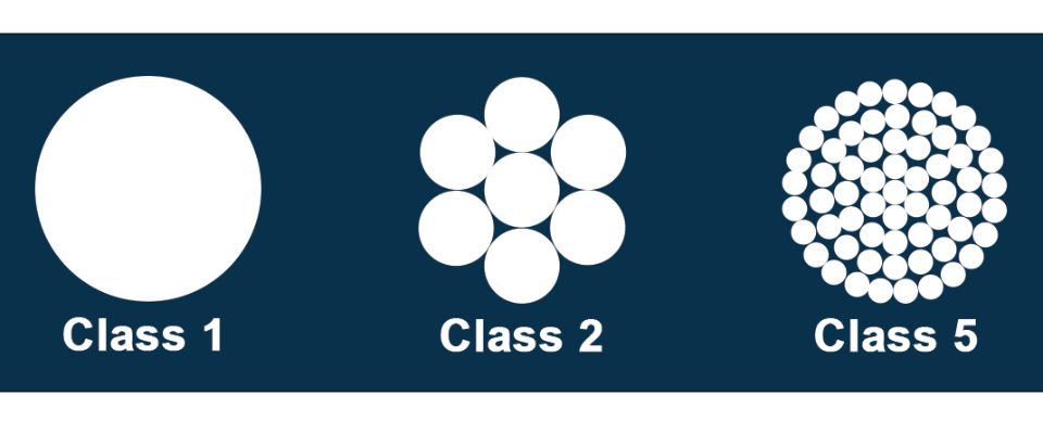
Cable cores are constructed according to the prescriptions of standard IEC 60228 and are divided into 4 classes, each with their own characteristics.
The nominal cross-section is in fact a codified way of indicating the resistance of the conductor.
If you’d directly measure on a particular conductor its diameter and then calculate its cross-section (diameter² / 4 x π), you’d notice that the result would slightly vary from the nominal cross-section.
Download the tables of the Classification of conductors according to IEC 60228
-
Class 1: solid conductor: the core is formed by 1 single wire.
The nominal section is determined by the maximum DC resistance of the conductor at 20°C. -
Class 2: stranded conductor: the core is formed by several wires that are stranded together into a "cord".
The nominal section is determined by a minimum number of wires and the maximum DC resistance at 20°C. -
Class 5: flexible conductor: the core is formed by a large number of thin wires.
The nominal section is determined by the maximum diameter of the wires and the maximum DC resistance at 20°C. Note that class 5 has a higher resistance than class 2 cores with identical section. -
Class 6: highly flexible conductor: the core is formed by even more and still finer wires.
The nominal section is determined by the maximum diameter of the wires and the maximum DC resistance at 20°C (Ω/km).
Classes 3 and 4 are not described in IEC 60228.
Download the tables "Classification of conductors according to IEC 60228".
-
Copper and tinned copper: class 1, class 2, class 5 and class 6 are defined.
-
Aluminium and aluminium alloys: class 1 and class 2 are defined. Classes 5 and 6 are not defined in IEC 60228.
Compacted Copper
You should always use the normal cable lug and die for the section, together with an extra splice sleeve to accommodate the smaller diameter, and not choose according to the measured diameter.
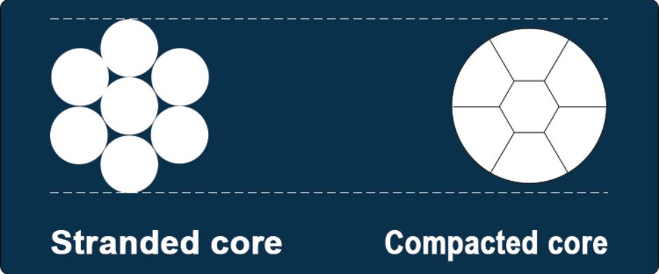
A compacted core has a smaller diameter than a non-compacted one, but both have the same resistance. The cable lug must be dimensioned accordingly.
A cable lug without a splice sleeve is not recommended. Although the input may be smaller, pressing with the die for the normal section risks to make insufficient contact. This increases the transition resistance, which is unfavourable.
Also remember to take into account the shape of the conductor. Round sleeves are available for round mono conductors. For 3-conductors with sectorial cores, there are sectorial sleeves with angle 120°; for 4-conductors, there are sectorial sleeves with angle 90°.
No. At Nexans, we always use compacted copper for the larger cross-sections from 70 mm² upwards, in all cable constructions with either round or sectoral conductors.
In the Belgian types, the cables with section 1.5 mm², 2.5 mm², 4 mm², 6 mm² and 10 mm² will never be compacted as they are constructed with a solid copper core (Class 1 according to IEC 60228).
For Class 2 cores according to IEC 60228, from 16 mm² upwards, the Belgian construction standards leave the choice between non-compacted or compacted cores. Whether a cable is compacted or not therefore depends on the cable manufacturer. For our Nexans cables the following rule applies:
-
All sectoral conductors are made up of compacted copper
-
For the round cores, all sections from 70 mm² upwards are made of compacted copper.
A compacted copper core is the result of a production process in which a Class 2 copper core, consisting of several round "wires", passes through a cold rolling mill. The empty space between the wires is squeezed out, so that the contact, and thus the conductivity, between the wires is optimal.
The process does not affect the resistance of the conductor and therefore the permissible current. In other words, with an identical section, a regular core and a compacted core carry the same amount of current. The diameter becomes smaller without changing the resistance. This makes the use of the correct connecting materials very important.
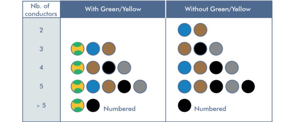
Colour coding acc. to HD308
-
Green/Yellow is for the protective conductor or earthing
-
Blue is for the neutral conductor
-
Brown, black and grey for the current-carrying or “live” conductors
The possible cable compositions are determined according to the number of conductors in the cable:
HD 308 S2 applies to:
-
electrical installations
-
distribution systems
-
the power supply of fixed or mobile current-using equipment
-
cords for portable equipment.
Not covered under HD 308:
-
the internal circuitry of machines
-
cables for DC applications
-
circuits that not only power machines
-
overhead lines
The installation cables according to the Belgian construction standard and the HAR cables follow the standardised colour code HD 308 S2.
HD 308 S2 - Identification of cores in cables and flexible cords is a standardised colour coding. This standard applies to the identification of cores of rigid and flexible cables and cords for which the rated voltage does not exceed 1 kV.
Cross-section determination
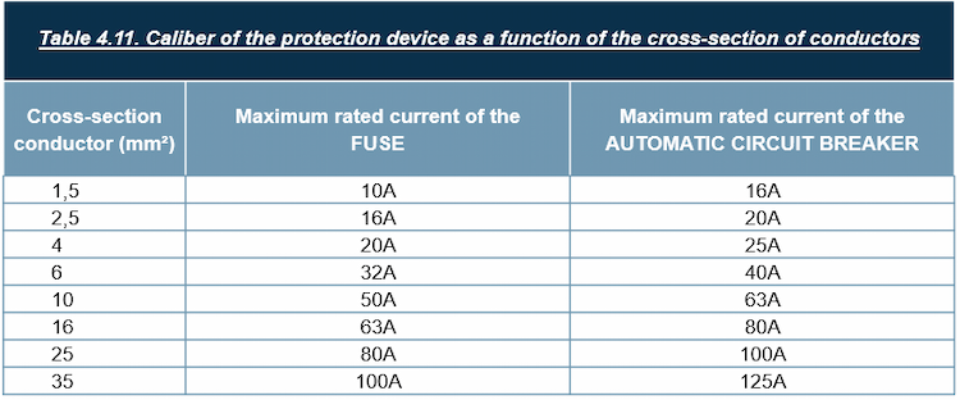
For domestic installations, the AREI/RGIE (General Regulation on Electric Installations) defines the maximum rated current of the fuses or the size of the automatic circuit breaker protecting a cable, according to the cross-sectional area of the conductors in Table 4.11.
This table does not apply to industrial installations.
When determining the section of fire-resistant cables, the increased resistance of the conductors and the increase in voltage drop due to the high temperatures that can be reached in a fire must be taken into account. The AREI/RGIE indicates that account must be taken of the compartment in which the greatest voltage drop occurs but it does not provide any concrete calculation method for the determination of the section.
The Wiedemann-Franz method is based on the laws of physics and takes compartments into account. The Wiedemann-Franz formula is only one of the possible approaches to the problem and in no way implies disapproval of other rules of good practice.
Download the calculation method (in Dutch or French only)
Not totally at ease with this calculation? Did you know EasyCalc also calculates the cross-section of fire-resistant cables? Its calculations are based on this Wiedemann-Franz method.
Suppose:
-
Required current = 125 A
-
3 phases + earthing 400V
-
Cable type XVB
-
Length = 15 m
-
Special features: The cable will be installed on a well ventilated cable duct, where two other energy cables are also laid (joined). The cable is installed in an area where the ambient temperature regularly reaches 40°C.
Application of the derating factors:
The initial cross-section determination indicates that an XVB 4G25 mm² is required to transmit a current of 125 A. This initial current of 125 A must then be divided by the derating factors based on the installation and environmental conditions:
-
derating due to high temperature: 125 A / 0.91 = 137.4 A
-
derating due to the proximity of adjoining cables: 137.4 A / 0.8 = 171.8 A
Conclusion: a section with an Iz higher than this result of 171.8 A should be taken. Concretely: an XVB 4G50 mm² which has an Iz of 192 A.
You don't want to have to do the calculations by hand each time? Did you know our free tool EASYCALC does it for you?
The proximity of other energy cables and other installation conditions influence the heating up of the cable. Therefore, the nominal load values must be combined with the various derating factors in order to adapt the current to the real situation.
A correct cross-section determination therefore takes into account both the required current and the derating factors. Please note that depending on the actual installation conditions, several derating factors may apply.
Download the derating factors for LV installation cables (in Dutch & French only)
The permissible maximum current - also designated by Iz or Imax - of a cable stated on the technical data sheets applies to the following standard conditions:
Laying underground:
-
Ground temperature: 20°C
-
Thermal resistivity of ground: 100 K.cm/W
-
Laying depth: 70 cm
-
Number of cables/system: 1, without other cables in the proximity.
-
Trefoil laying for single core systems.
Laying in air:
-
Ambient temperature: 30°C
-
Installation on an open and ventilated cable tray
-
Number of cables/system: 1, without other cables in the proximity (not in a bundle or layer)
-
For XGB and XVB single cores: based on 3 conductors in trefoil
-
For H07Z1-U & -R and H07V-U & -R based on 3 conductors in conduit, integrated in a wall.
Derating factors must be applied in all other installation conditions.
Our tool for cross-section determination EASYCALC takes the right derating factors into account when determining a cross-section.
When calculating the cross-section, you should take into account:
-
Heat:
-
The selected section must be such that the heating caused by the currents passing through it does not exceed the allowed conductor temperatures. Overloading the cable must be prevented.
-
One or several derating factors must be applied according to the actual laying circumstances and environment of the installation in order to take into account the actual currents in service.
-
-
Voltage drop:
-
A voltage drop of 5% is generally permitted.
-
The distribution system operator can impose a maximum voltage drop of 3% in certain situations.
-
Higher voltage drops are allowed for the starting of motors, where high inrush currents can occur.
-
Our websites
Select your country to find our products and solutions
-
Africa
- Africa
- Ghana
- Ivory Coast
- Morocco
- North West Africa
- Americas
- Asia
- Europe
- Oceania